Gears & Mechanisms
Educational Gear Examples 4
SKU 3DPW-pr-1480675
$67.00NZD
In stock · Made-to-order resin · Ships from Auckland · Free shipping over $75
- Material
- High-Detail Resin (8K)
- Colour
- Grey
- Weight
- ~40 g
- Print time
- ~4.5 h
- Shipping
- $10 std · $20 express
- Lead time
- 1-3 d print + 1-4 d ship
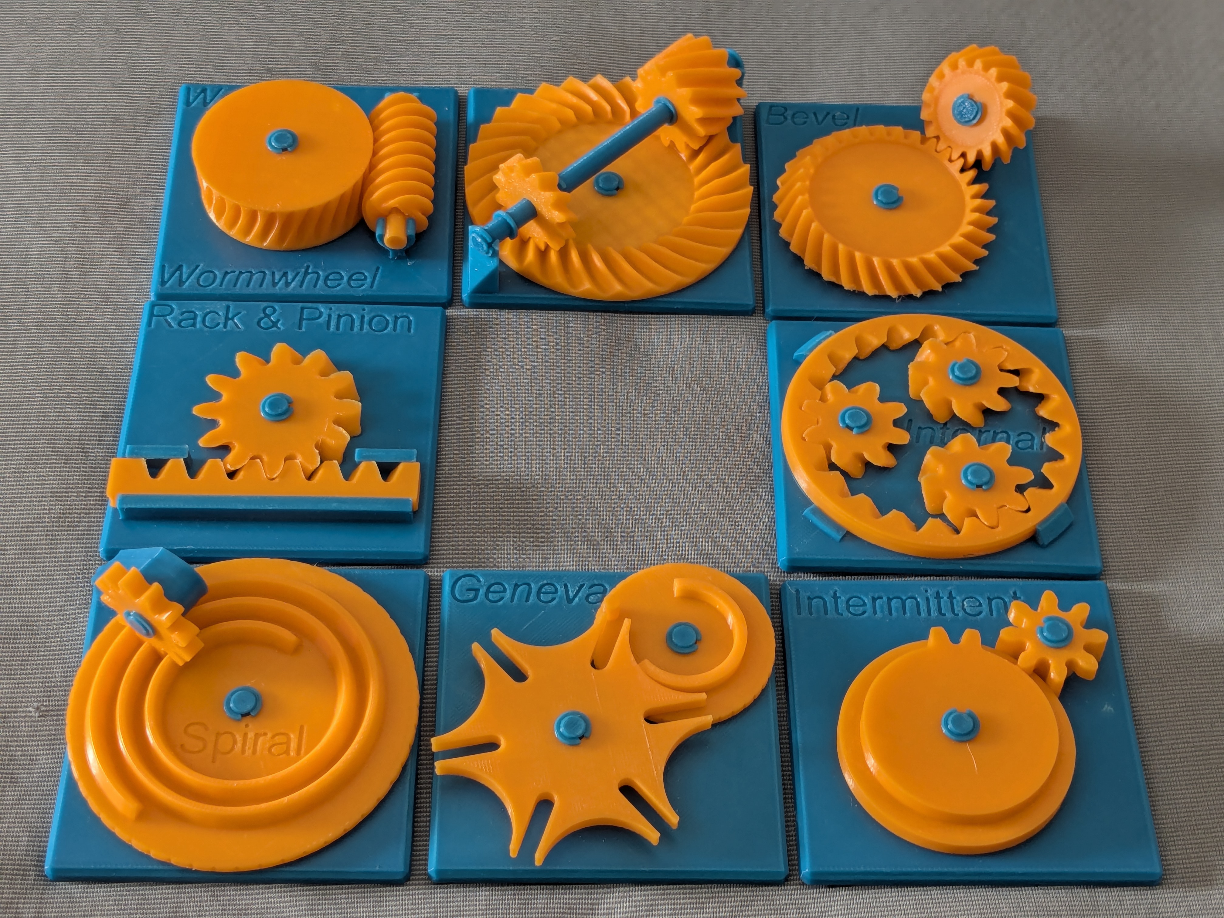
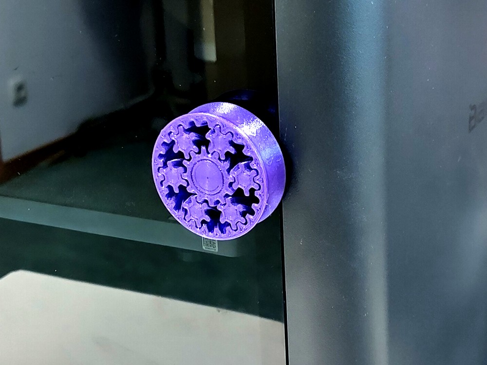
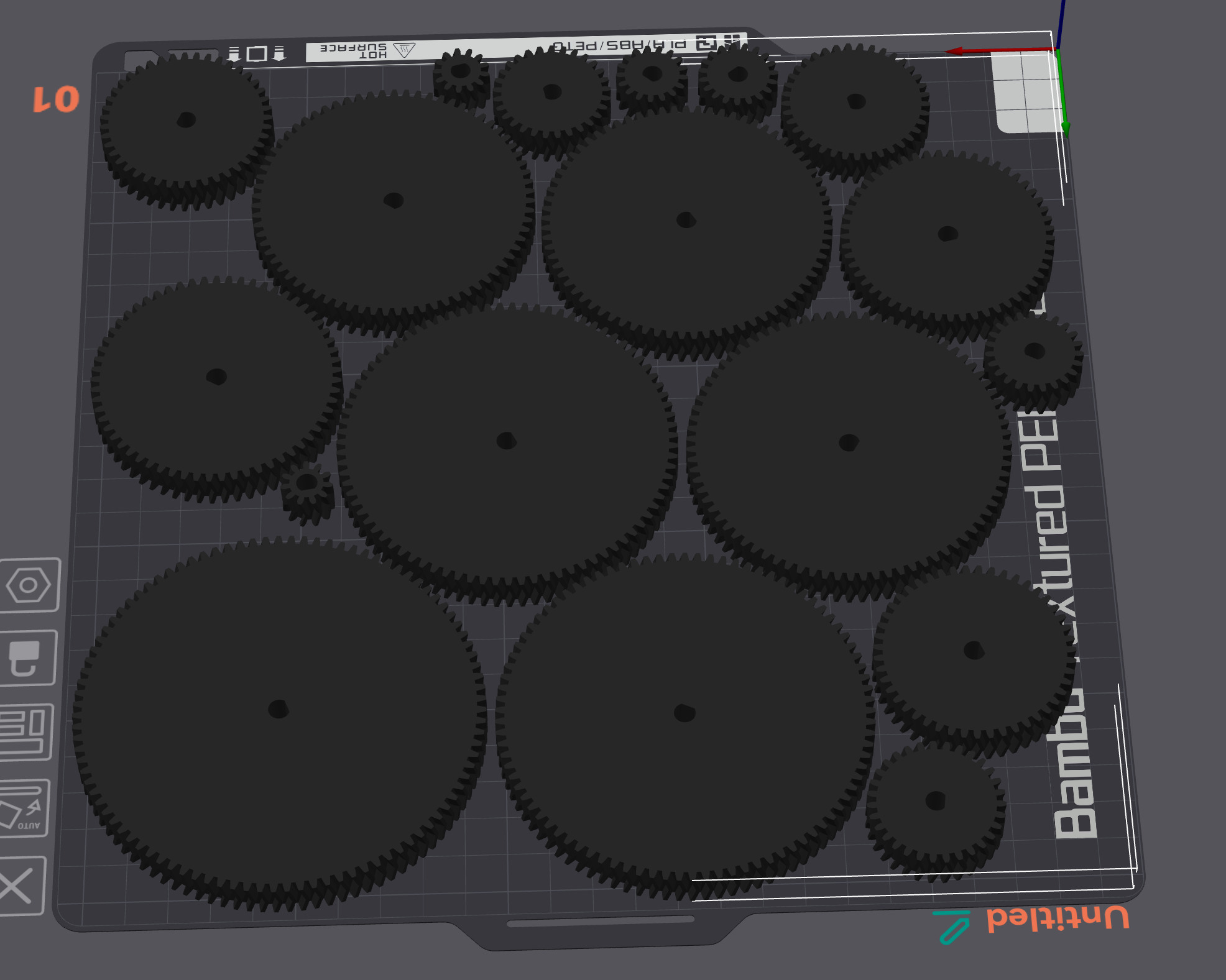
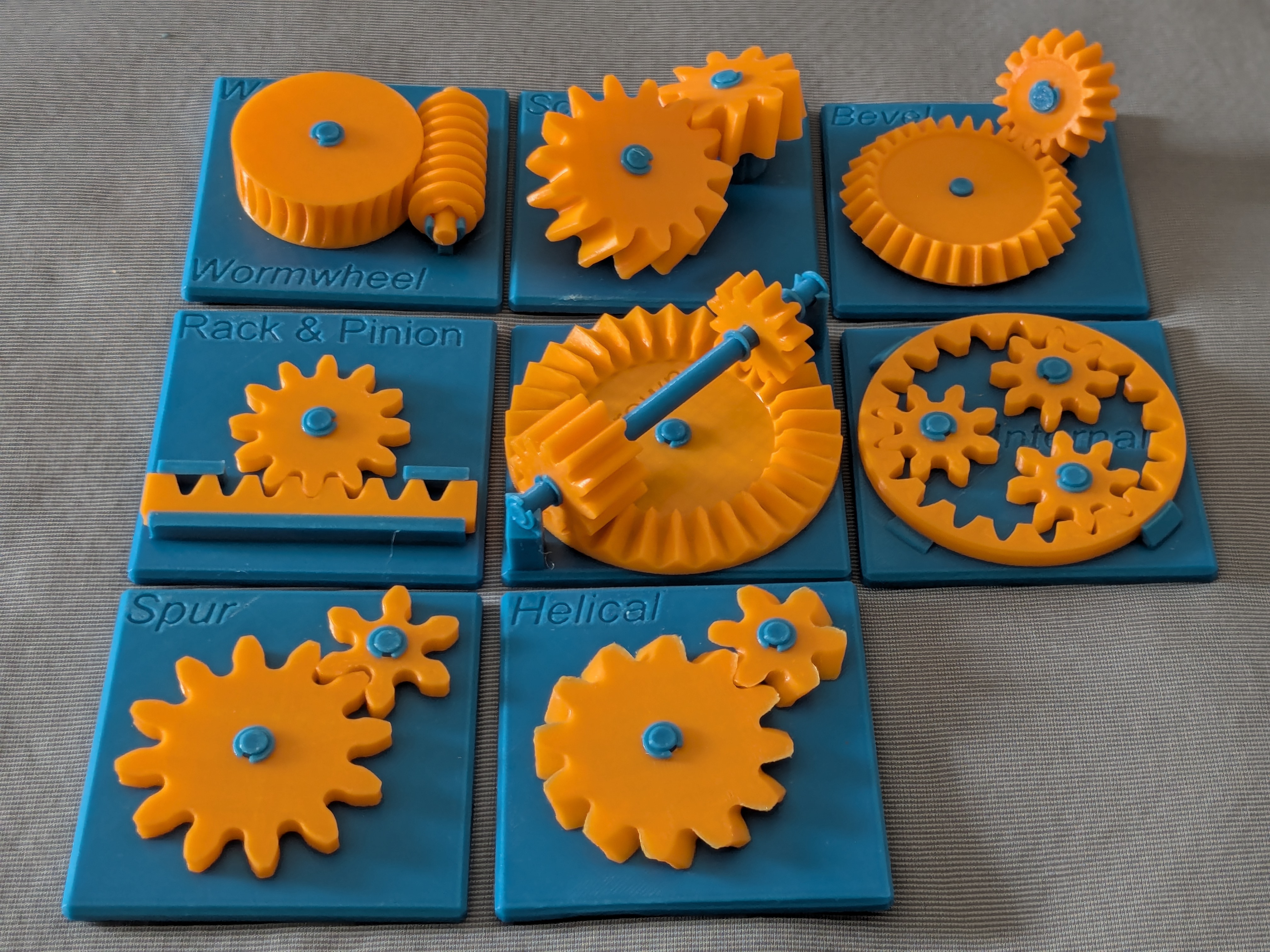
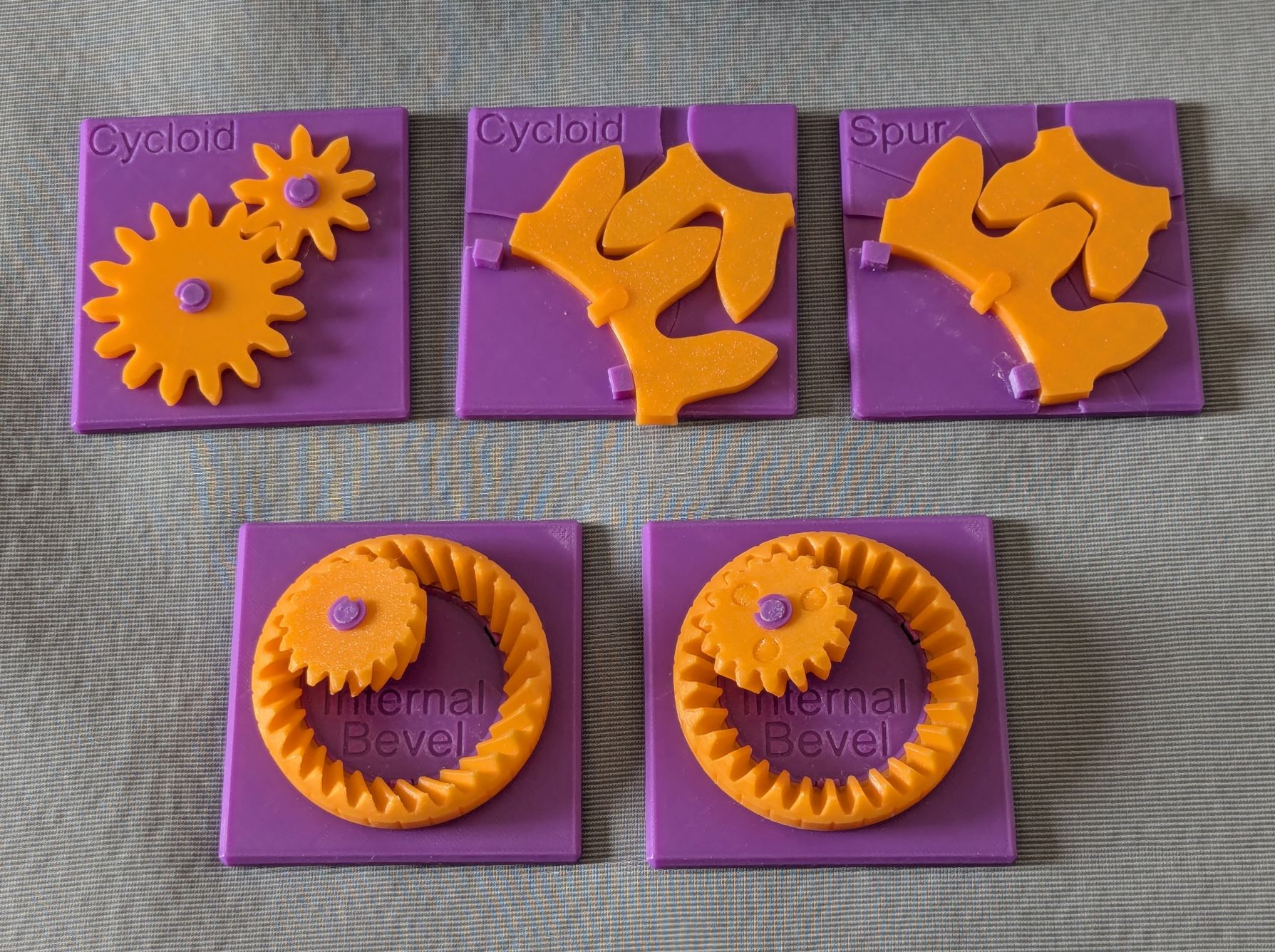
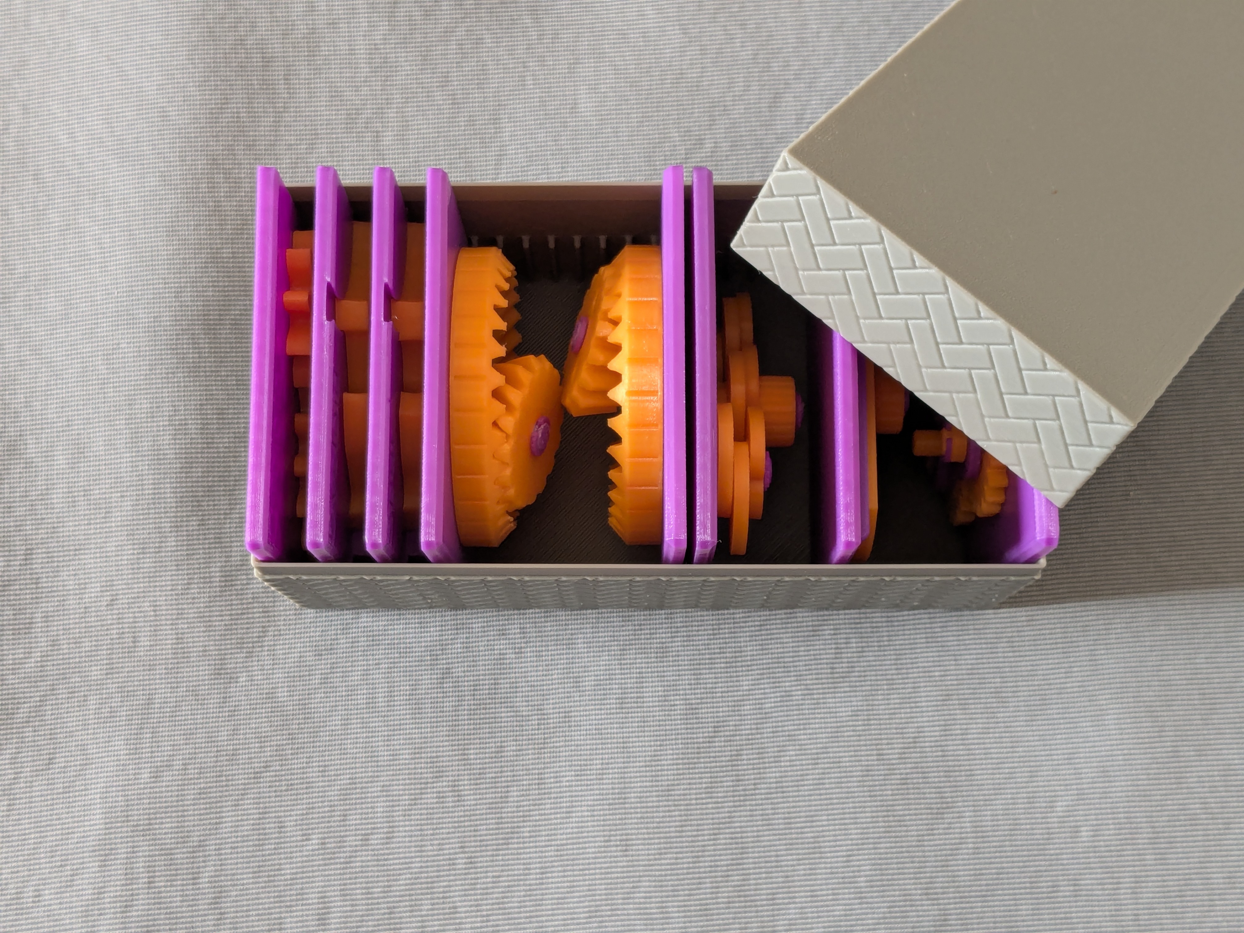
My Educational Mechanical Examples SeriesThis model is one of my educational mechanical mechanism examples on 80mm x 80mm base plates. You can find all models of the series in this collection => [Mechanical Mechanism Examples] This setThis present set includes: Cycloid gearMagnified cycloid gearMagnified involute gearInternal bevel gear with straight teethInternal bevel gear with spiral teethBrief descriptionThe cycloid gear shown here is another type of spur gear. While the most common spur gear is the involute gear—whose working tooth profile is generated from the involute curve—the cycloid gear is typically used in precision machinery such as watches, where loads are relatively light and efficiency is critical. The tooth profile of a cycloid gear consists of two cycloid curves. Here, a cycloid is traced by a point on a rolling circle that rotates without slipping on the pitch circle, not on a straight line. The external portion of the tooth profile is an epicycloid, generated by a circle rolling on the outside of the pitch circle.The internal portion is a hypocycloid, generated by a circle rolling on the inside of the pitch circle.The two rolling circles do not need to have the same radius. However, for a pair of cycloid gears to mesh correctly, the radius of the rolling circle used for the internal hypocycloid of one gear must match the radius of the rolling circle used for the external epicycloid of the mating gear. In practice, the rolling circle for the internal hypocycloid is often chosen to be about one third of the pitch-circle radius. Compared with involute gears, cycloid gears have fewer contact points and less sliding motion, resulting in very low friction. On the other hand, they are more difficult to manufacture, have lower tooth strength, and require precise center-to-center alignment. For these reasons, cycloid gears are used mainly in high-precision, low-load, and high-value applications such as mechanical watches, where minimizing loss is essential. To compare the tooth profiles of involute gears and cycloid gears, magnified models are provided. The lines and curves engraved on the base plate show the paths traced by the contact points between the meshing teeth. You can observe that, in involute gears, the contact points move along straight lines, whereas in cycloid gears, they move along circular arcs. You can find non-magnified model of involute gears in my first set of gear examples. As described before, the two axes of mating bevel gears can have an arbitrary angle. Here, I provided the models of internal bevel gears, where the angle between the two axes is close to 180deg. They are still meshing perfectly as you can feel by rotating them. CaseThese models are compatible with the case included in my first set. PrintingUse the models named ???-printable.stl for printing. The models named ???-assembled.stl are provided just to show how they should be assembled. Use well-dried PETG to have better dimensional accuracy.Use 0.1 mm or 0.08 mm layer height to have smoother surfaces.Use slow printing speed for overhangs.Select “Random” seam position to have smoother rotation. Randomly distributed seam should be easily worn out after some wearing.Sanding and FilingSometimes, the gears suffer from the stringing effect and/or elephant foot effect, resulting in a too tight fit to the shafts (they are designed with a 0.15 mm radial clearance). If you see rough surface on the shafts due to stringing, sand off the roughness with a small piece of sand paper. If you feel the gears do not rotate smoothly due to an elephant effect, widen the hole slightly by using a thin round bar file. Without those issues, the gears should rotate very smoothly with minimal friction. AssemblyNo glue is needed. Just snap the retaining rings onto the shafts for cycloid gears and bevel gears. For magnified models, slide in the teeth first, and then lock the larger gear by the key. Other educational modelsYou may also be interested in the models in my educational mechanical mechanism examples. Find them in this collection: https://www.printables.com/@osamutake_3341417/collections/2728214 AcknowledgementI got into gears thanks to K.$uzuki's amazing articles and YouTube videos. Many of the mechanisms shown here came from the introductions on his website. He also makes excellent gear models himself. This series wouldn’t have existed without his inspiration. I learned a lot about technical detail of designing gear tooth profiles from Haguruma-No-Hanashi website. I’m truly grateful for that.Happy printing!
Tags: gear, education, educational, resin print, nz made, made to order
Design credit: Original design by osamutake - licensed under CC-BY.
View original model + STL files on Printables ↗
View original model + STL files on Printables ↗
Frequently asked
How long does shipping take?
Educational Gear Examples 4 is printed to order. Lead time is typically 1-3 business days plus 1-4 days NZ shipping. Standard NZ shipping is $10, free over $75.
What material is this printed in?
By default this is printed in High-Detail Resin (8K) at 0.025 mm layer height on an MSLA resin printer. Custom material and colour swaps are available, just leave a note at checkout.
Can I get this in a different colour?
Yes. Every product can be printed in any of the resin colours we stock, or hand-painted on request. Leave a note at checkout or email [email protected].
Do you ship outside of New Zealand?
Currently New Zealand only. Australian shipping is coming.
Who designed this?
Designed by an independent sculptor and licensed for commercial printing. The original is linked on this page.